

Check the detailed pre-sales guide to find the right device for you and upgrade your intercom with smart home control with confidence.
Key Takeaways
- Make sure there is an intercom circuit at home.
- Make sure your lock and gate opener are compatible if you need to control the lock and gate with Tapo D315 KIT.
- Tapo D315 KIT supports three power options. Choose the one that suits your home.
- You can also find the installation guide in the Tapo app.
What You Should Know Before Purchasing the Smart Video Intercom 2K Pro (Tapo D315 KIT)
The Tapo D315 KIT is a smart video intercom system that adds smart home control to your intercom. It lets you monitor what’s happening outside, lock and unlock without going out, and open the driveway gate with a tap for your family. The indoor screen can also work as a central hub to control other Tapo smart sensors and cameras.
Check the wiring instructions below to determine whether Tapo D315 KIT fits your home.
1. Check Wiring Compatibility
Tapo D315 KIT can replace your existing intercom system or be wired to your reserved intercom circuit. Before purchasing, please confirm that your existing intercom wiring supports a 2-wire connection between the indoor and outdoor units. The table below provides installation recommendations based on common cable types you may have at home.
|
Wire Type |
Reference Image |
Wiring Method |
|
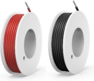
Single-core wire |
|
Connect each wire to a terminal. |
|
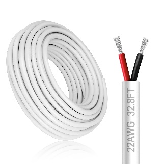
2-core wire |
|
Connect the two cores of the wire to the + and - terminals separately. |
|
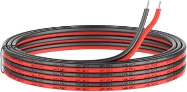
Parallel wire |
|
Connect each wire to a terminal. |
|
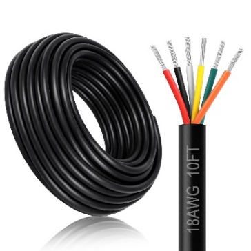
multi-core cable: 4-core cable/6-core cable/8-core cable |
|
Connect any two cores of the wire to the + and - terminals separately. Ensure they are the same length and have the same twist. After connection, if the intercom system restarts, fails to display the live view, or shows other issues, please contact Technical Support. |
|
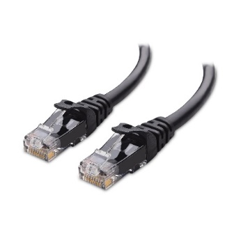
Cat 5 (or higher) Ethernet cable |
|
Cut open the Ethernet cable's outer jacket. Connect the two wires of one twisted pair to the + and - terminals separately. If the wiring distance between the indoor and outdoor units exceeds 60 m, you may connect two twisted pairs to the terminals. |
|
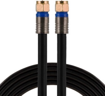
Coaxial cable |
|
Cannot be used to connect the indoor and outdoor units. Upgrade your circuit before purchasing. |
2. Check Existing Typology
The key is to check whether the indoor unit is directly connected to the outdoor unit without any contacts in between. Tapo D315 KIT works when the indoor unit is directly connected to the outdoor unit, as the following typology shows:

Please contact our Technical Support or consult a qualified electrician if your existing typology is included in, but not limited to, the situations below:
1) There is an intermediate node used for power supply and signal processing between the indoor and outdoor units.
2) One indoor unit is connected to multiple outdoor units or incompatible devices such as lights and chimes.
3) One outdoor unit is connected to multiple indoor units or other incompatible devices such as streetlights and cameras.
4) A power supply is connected to the outdoor unit.
3. Check the Power Options
Tapo supports two power options (depending on the accessories provided). If the following two options do not suit your home, contact TP-Link Technical Support for more solutions.
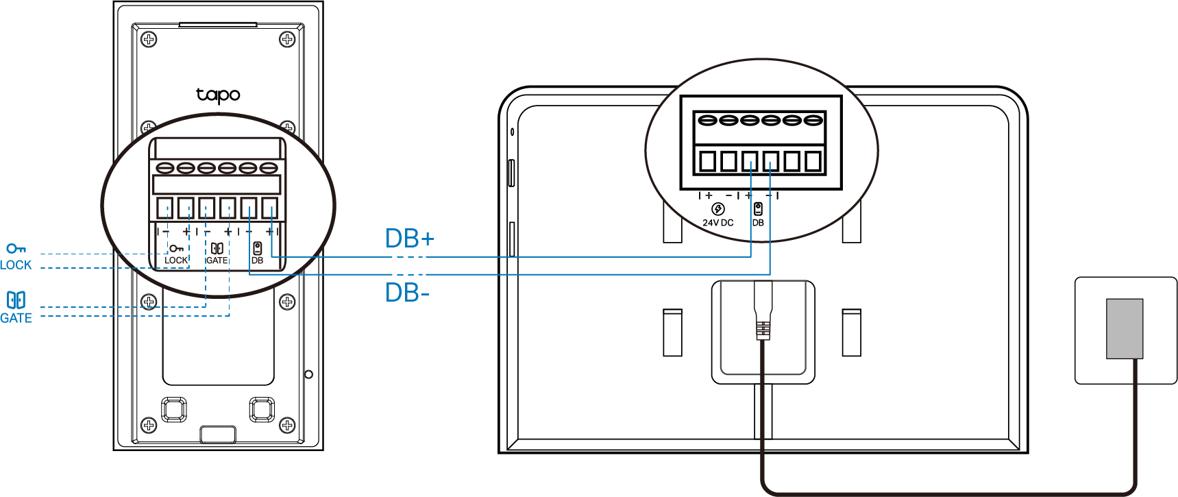
Power option 1: Use the provided power adapter
If you have a power outlet near the indoor unit, you can use the provided power adapter to power your device. The wiring typology is as follows:
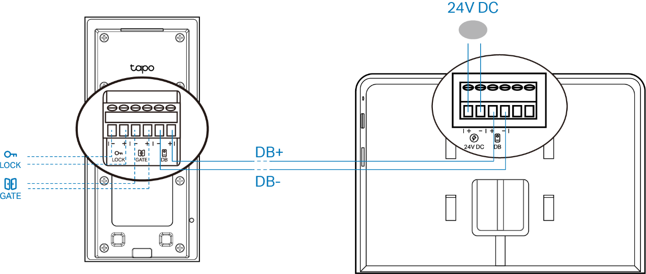
Power option 2: Use the reserved 24V DC (at least 1.5A) power supply and wires
If you have reserved the 24V DC (at least 1.5A) power supply and wires, you can connect the wires to the indoor unit to power your device. The wiring typology is as follows:
4. Check the Lock and Gate Compatibility
For Connection to a Lock
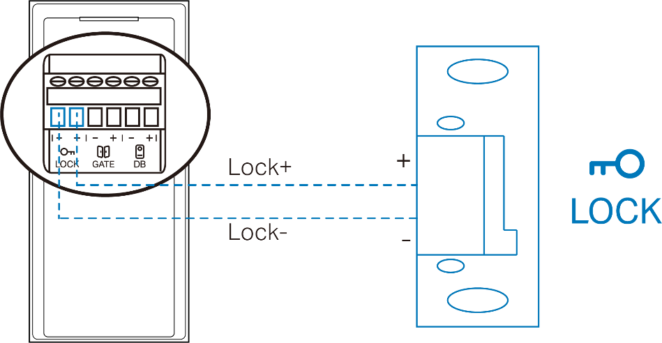
1) Only distinguish between the positive and negative terminals if your lock requires it.
2) Your lock must have a mechanical memory.
3) Your lock must be a normally closed (NC) one.
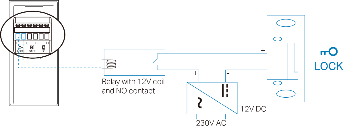
4) The power supply to the lock must NOT exceed 12V/1.1A.
5) If the power supply exceeds 12V/1.1A, follow the diagram below:
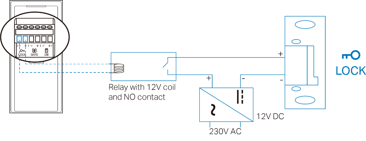
6) Your lock should not have an extra power supply before wiring to avoid damaging the device. If there is an extra power supply, you have two options:
Option 1: Use a 12V, NO relay to rebuild the circuit.
Option 2: Remove the extra power supply and ensure the lock meets the other requirements above.
For Connection to a Gate Opener
If you need to use the intercom to control a vehicle gate, please make sure the gate’s control panel still has an available control port for the intercom to connect to. During installation, refer to the vehicle gate’s manual. If you have any questions, please contact our Technical Support.
1) No need to distinguish between the positive and negative terminals since the intercom panel provides a dry-contact connection to the automated gate.
2) Breaking capacity for gate control: 12V DC / 2A.
5. Check If There Is Enough Space for Installing the Outdoor Unit
Before installation, make sure the hole in the wall has enough space to accommodate the wires and wire connectors. For the indoor unit, this means 4 wires plus wire nuts; for the outdoor unit, 6 wires plus wire nuts. If space is insufficient, enlarge the hole in advance.
6. Get to Know the Wiring Terminals on the Indoor and Outdoor Units
For the Indoor Unit
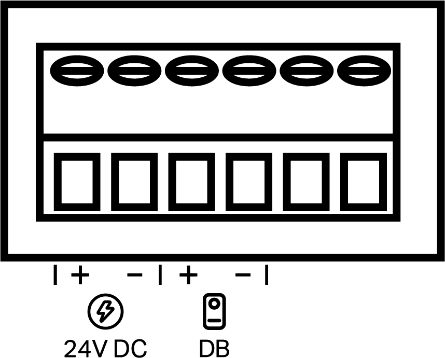
The 24V DC +/- terminals are used for connecting to a 24V DC (at least 1.5A) power supply
The DB +/- terminals are used to connect the intercom panel to the screen, providing power and network to the intercom panel.
For the Outdoor Unit
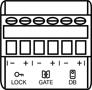
The LOCK +/- terminals connect the wires that unlock the pedestrian gate.
The GATE +/- terminals connect the wires that open the driveway gate.
The DB +/- terminals connect the intercom panel to the screen, providing power and network to the intercom panel.