Follow the installation instructions below to install your Smart Video Intercom 2K Pro. Upgrade your intercom with smart home control with confidence.
Key Takeaways
- Make sure there is an intercom circuit at home.
- Make sure your lock and gate opener are compatible if you need to control the lock and gate with Tapo D315 KIT.
- Tapo D315 KIT supports three power options. Choose the one that suits your home.
- You can also find the installation guide in the Tapo app.
Installation Guide
1. Check Wiring Instructions
1) Cut off power before wiring.
2) To prevent interference and malfunction, do not run the video intercom kit wires through the same sheath as the electrical wires.
3) The length and twisted state of the wiring connecting the intercom panel and screen must be kept consistent.
4) If using the reserved power supply, make sure it is rated for 24V DC (at least 1.5A).
5) Only use compatible wires with a flammability rating of at least VW-1. Refer to the wiring specifications below.
|
|
Ø 2 x 0.75 mm² |
Ø 2 x 1.5 mm2 |
Twisted Pair* |
|
|
0-50 m |
0-100 m |
up to 120 m |
|
|
1-10 m |
1-10 m |
1-10 m |
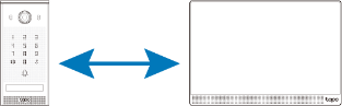
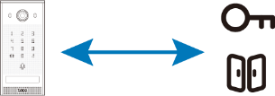
*Use Cat 5 or higher cables and merge the two wires of a single twisted pair into one terminal. If you use each wire within a twisted pair independently, the maximum distance is 60 m.
6) When wiring, make sure the exposed wire sections do not touch each other to avoid damaging the device. If your wires are too thick and the exposed parts may touch, there are two solutions:
Solution 1: Adjust the thickness of the cable:
Solution 2: Connect it to a provided wire using the provided wire nut:
For Connection to a Lock
1) Only distinguish between the positive and negative terminals if your lock requires it.
2) Your lock must have a mechanical memory.
3) Your lock must be a normally closed (NC) one.
4) The power supply to the lock must not exceed 12V/1.1A.
5) If the power supply to the lock exceeds 12V/1.1A, follow the diagram below:
6) Your lock should not have an extra power supply before wiring to avoid damaging the device. If there is an extra power supply, you have two options:
Option 1: Use a 12V, NO relay to rebuild the circuit.
Option 2: Remove the extra power supply if the lock meets the requirements above.
2. Install the Intercom Panel
1) Cut off power first. Unscrew your existing intercom panel and pull it out to expose the wires. Apply the provided wire labels to the corresponding wires based on the intercom panel's terminals.
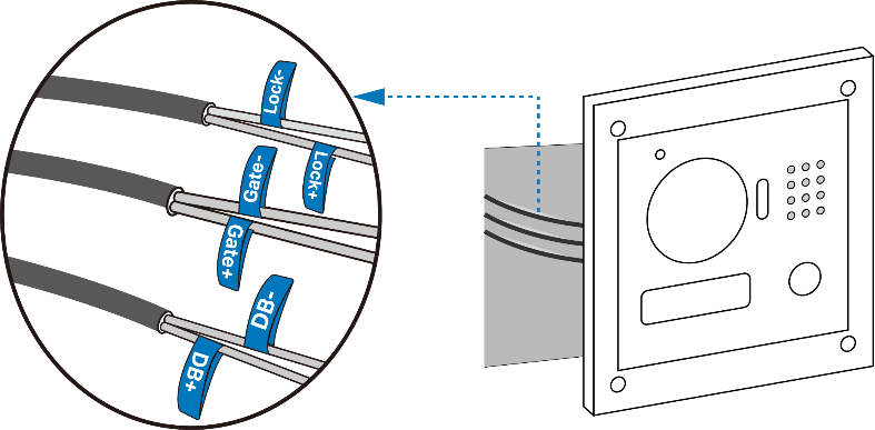
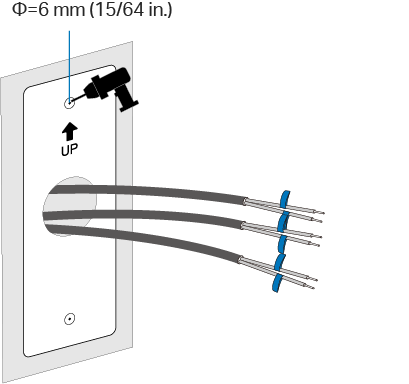
2) Remove the existing intercom panel. Route the wires through the mounting template sticker for the intercom panel, and apply the sticker 1.6 m/5.25 ft from the ground. Drill two holes according to the sticker.
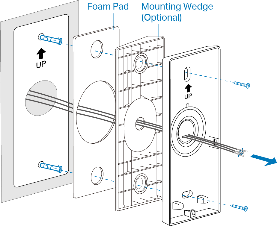
3) Insert two anchors into the holes. Stick the foam pad on the back of the bracket. If you use the wedge to adjust the viewing angle, stick the foam pad to the wedge. Then, use screws to fix them to the anchors.
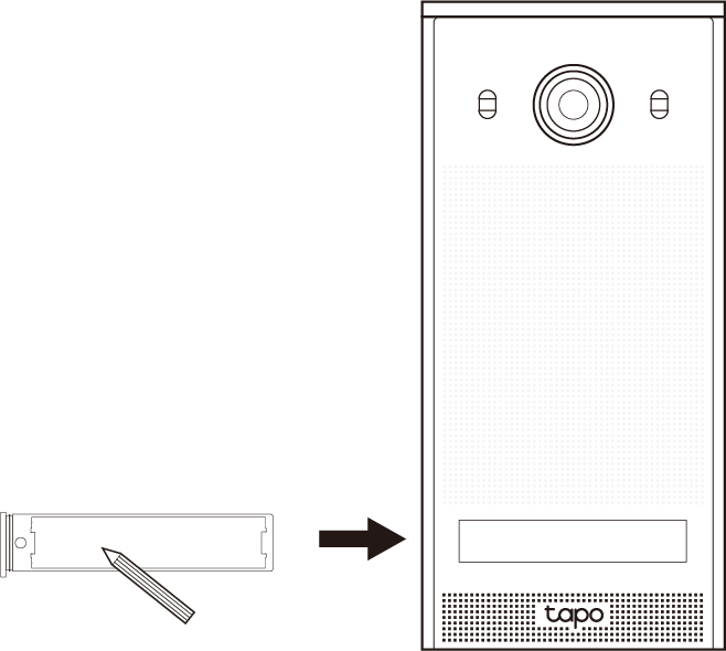
4) Pull out the name card and sign your name. Then put it back.
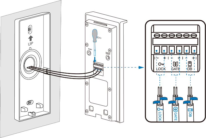
5) Connect the wires to the intercom panel with the help of the labels.
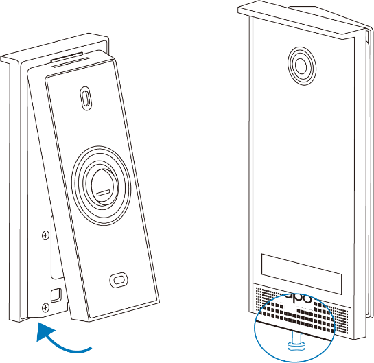
6) Align the tab on the intercom panel with the slot on the bracket and attach the intercom panel from top to bottom. Then use the provided screwdriver to tighten the screw at the bottom of the intercom panel.
3. Install the Smart Screen
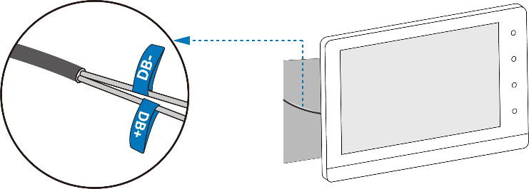
1) Cut off power first. Unscrew your existing screen and pull it out to expose the wires. Apply the provided wire labels to the wires based on the screen's terminals. Then, remove the existing screen.
Note: If there are reserved 24V DC (at least 1.5A) wires, apply DC wire labels.
2) Install the mounting bracket.
Case 1: If the wires come directly out of the wall
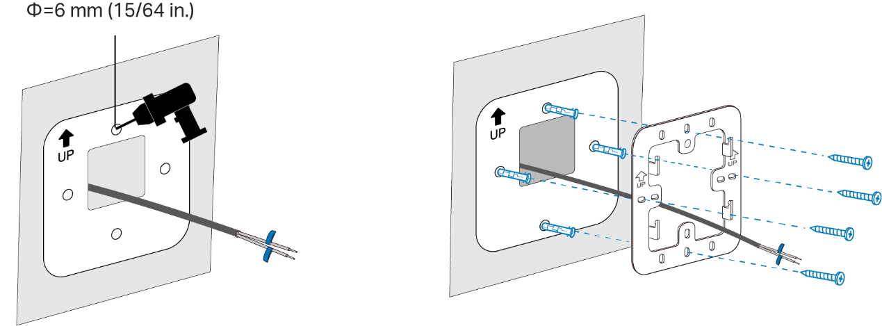
Route the wires through the screen’s mounting template sticker and drill four holes as shown on the sticker. Then insert four anchors into the holes. Use screws to fix the bracket over the anchors.
Case 2: If there is a junction box
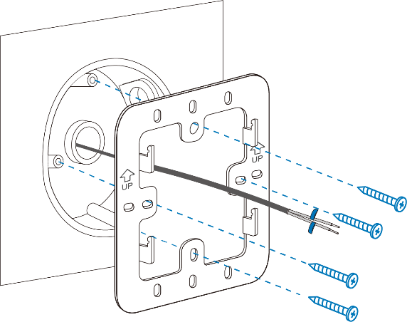
Route the wires through the opening of the screen’s bracket, and align the bracket with the junction box to locate the appropriate screw holes. Use the screws on the box to secure the bracket.
3) Connect the wires with the help of the labels.
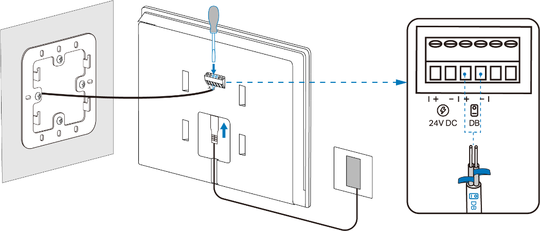
Power Option 1: Plug in the power adapter.
Loosen the fixing screws for the DB terminals by turning counterclockwise with the provided screwdriver. Insert the wires and tighten the screws. Make sure they are properly connected. Then plug in the power adapter.
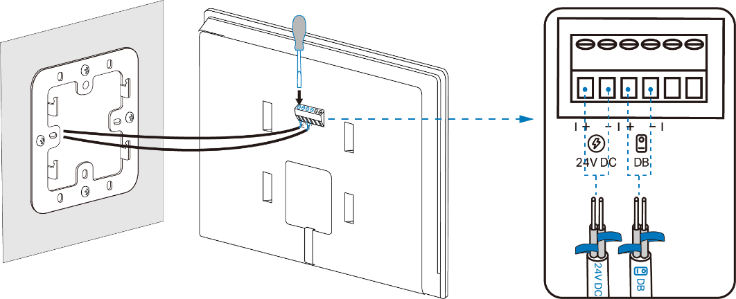
Power Option 2: Use the reserved 24V DC (at least 1.5A) power supply and wires.
Loosen the fixing screws for the 24V DC and DB terminals by turning counterclockwise with the provided screwdriver. Insert the wires and tighten the screws. Make sure they are properly connected.
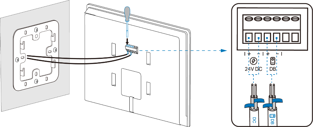
Power Option 3: Use the jack connector cable + power adapter when the power supply you reserved is not 24V DC (at least 1.5A).
a. Loosen the fixing screws for the 24V DC and DB terminals by turning counterclockwise with the provided screwdriver. Insert the wires and tighten the screws. Make sure they are properly connected.
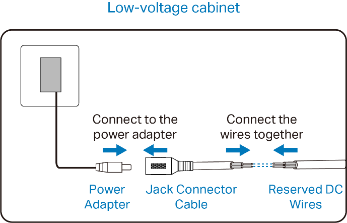
b. Find the DC wires in the low-voltage cabinet and connect them to the jack connector cable, and then connect the jack connector to the power adapter’s connector. Plug in the power adapter.
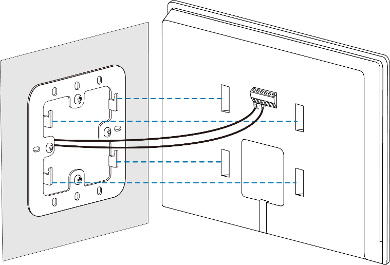
4. Secure the Screen
Align the wall-mounting holes on the back of the screen with the hooks on the bracket and slide it down until it clicks. Turn on the circuit breaker to power on your device. The screen should turn on.